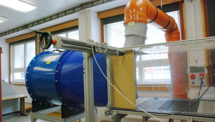
The goal was the development of the experimental setup for the study of radial flow velocity component effect on the aeroelastic stability of a blade cascade. The radial flow is achieved by a secondary (bypass) tunnel, connected to the main one.
The channel flow around the blade cascade with fixed blades at the bottom and free ends at the top was investigated by using PIV technique.
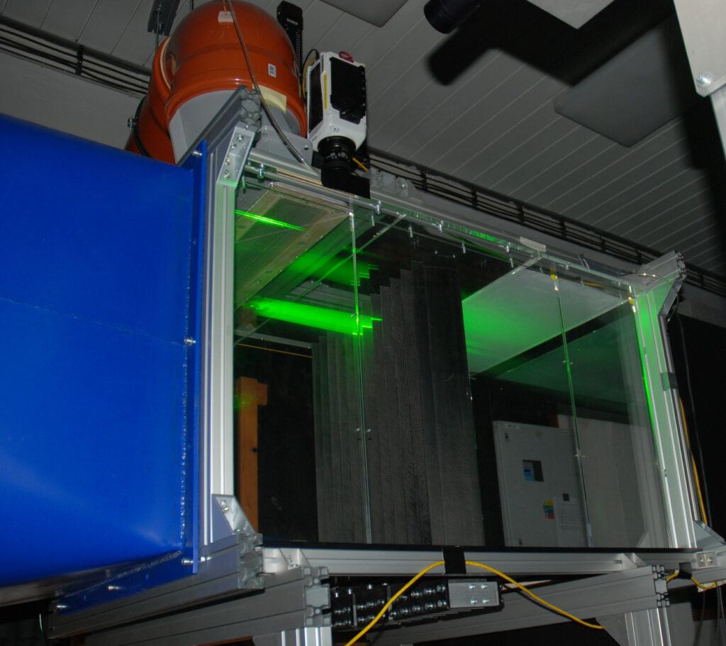
Figure 1a – PIV measurement of in horizontal planes
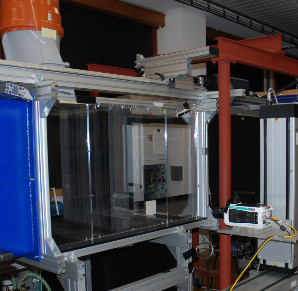
Figure 1b – PIV measurement of in vertical central planes
To ensure flow quality, the wind tunnel with bypass flow was tested without blades to prove a uniform velocity profile. For flow stabilization, a fine mesh and two honeycomb plates were added to reduce large vortices, resulting in a significantly more stable flow. Finally, visualization using smoke was used to assess the magnitude of the radial flow component under various main-to-bypass flow ratios.
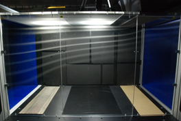
Figure 2 – Flow visualization using smoke, the bypass flow rate set to 20 % of the main channel flow
Measurement of the free flutter
We began with free tests of blade cascade oscillation, where the blades were clamped at the bottom and free at the tip. The blade cascade response to the flow field instability was examined using a fast CMOS camera (sampling frequency 1 kHz). The instantaneous images of blade tips were analyzed using Image Processing methods. Initial tests proved that bypass flow causes vibration of blades fixed at the bottom end and free at the top end.
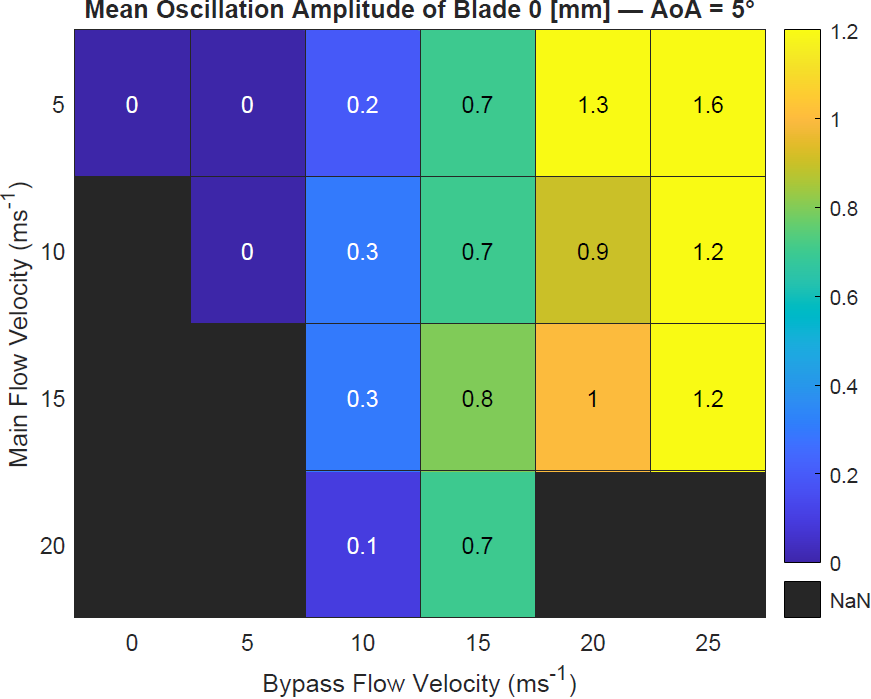
Figure 3 – Mean oscillation amplitude of blade 0 for various combinations of main tunnel and bypass tunnel velocities
Controlled Flutter & Instrumentation
This stage required active control of the blade’s motion to simulate travelling waves using a pair of electromagnets. The elastic suspension utilizes two flat metal sheets and a metal rod forming a special parallelogram, allowing motion perpendicular to the chord and rotation while restricting chordwise motion. The flat metal sheets are equipped with strain gauges calibrated to measure the displacement and angular displacement of the blade root. Excitation of the blades is provided by a pair of electromagnets on each blade that can excite vibration in both degrees of freedom. Under each electromagnet coil there is a force cell to measure the excitation force. The control algorithm was developed and tested in Simulink environment and runs on dSPACE SCALEXIO hardware.
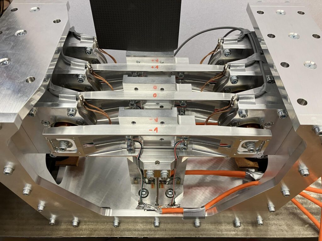
Figure 4 – Elastic suspension of the three middle blades with excitation and measurement instrumentation